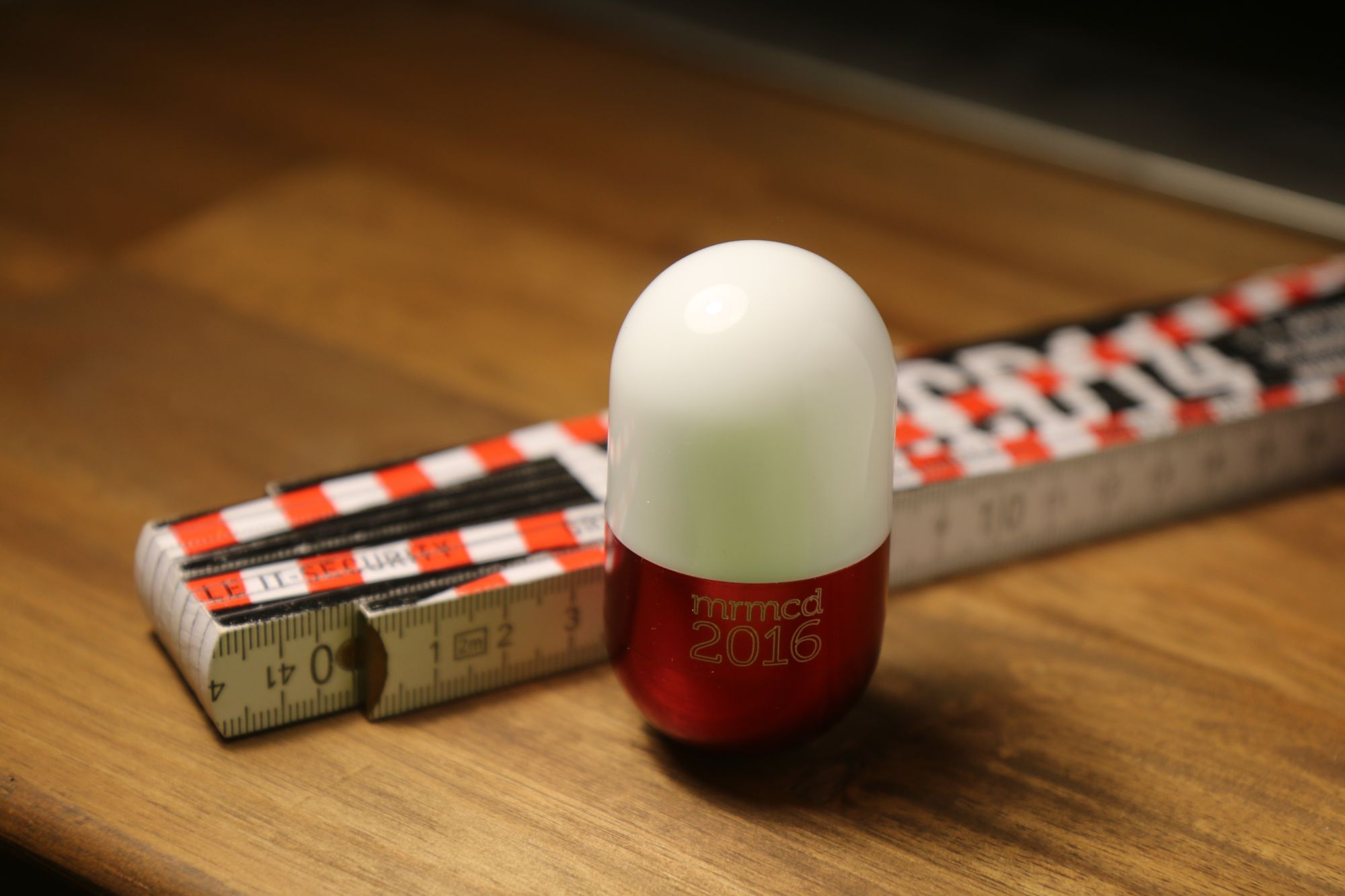
McCoy is a side project I made to learn how to use the ATtiny microcontroller. The Idea came about at MRMCD2016, when I received a welcome gift in form of a light-up LED Pill. The very first thing crossing my mind was to put more electronics into this tiny housing.
What’s inside?
Originally, it contained a very simple PCB with five leds. It still contains a pair of 2032 Lithium Batteries (2x3V) and a nice on-off-switch at the bottom. It is basically a flashlight in form of a aluminum/plastic pill.
Now it contains an extra PCB with a bunch of LEDs and a microcontroller:
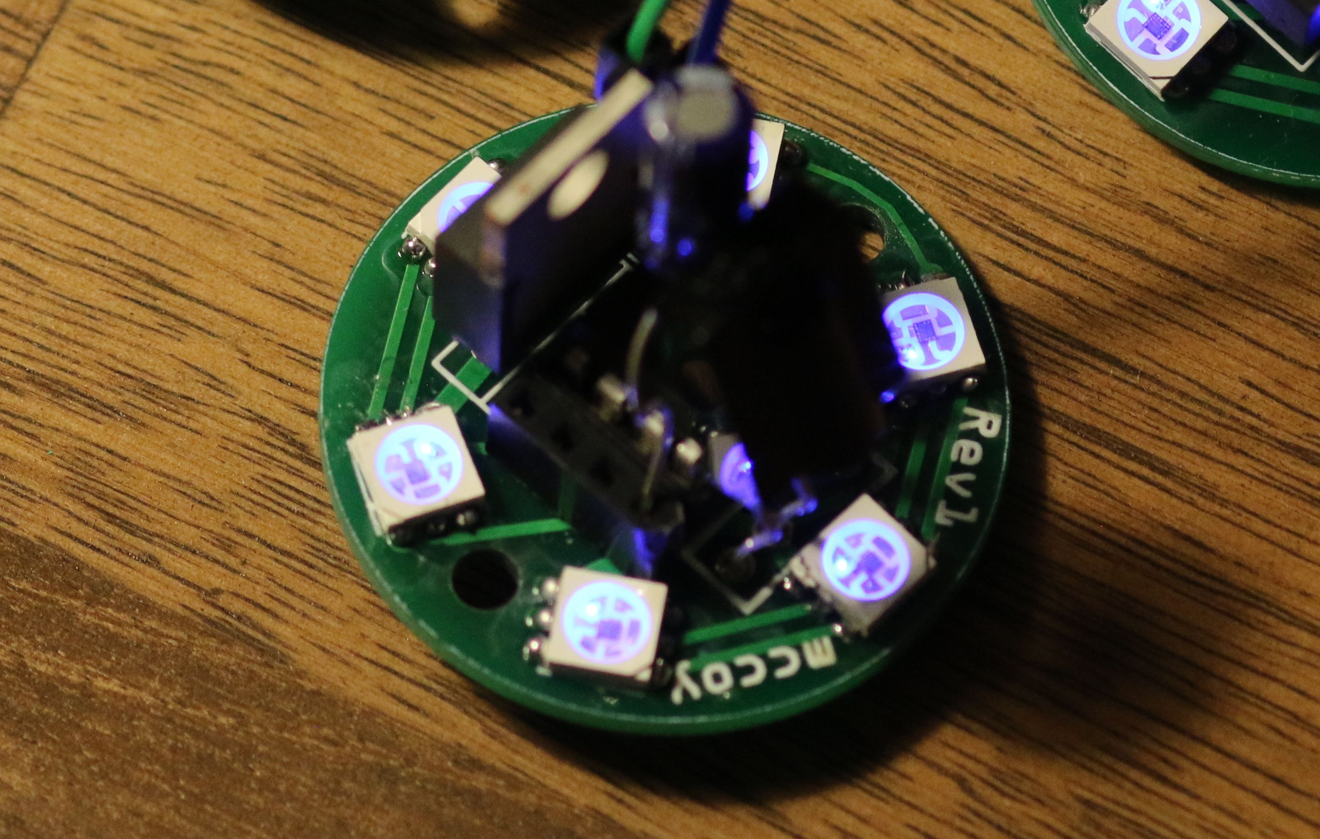
- specialized PCB
- 6 APA102 RGB LEDs
- ATtiny85 microcontroller
- LM2940 LDO 5V Regulator
- TSOP31238 Infrared receiver
- stabilising capacitor
Breadboard Stage
I’m using an arduino to program my ATtiny. There’s tons of great tutorials out there, so I’m not going into the details here. I followed this ATtiny-Arduino-Howto by High-Low Tech, which is very detailed. Here’s also a video showing you how to set up an Arduino as a programmer for the ATTiny, but it is not as detailed.
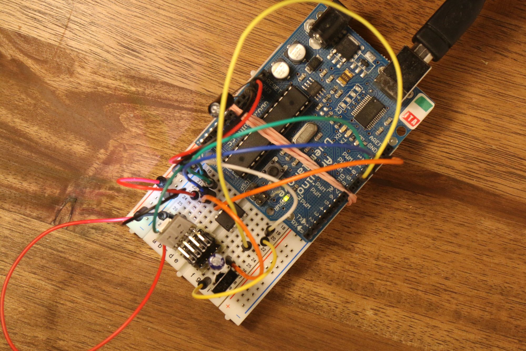
This mess of wires is actually just this, if you remove the programmer-part (and redraw it in fritzing):
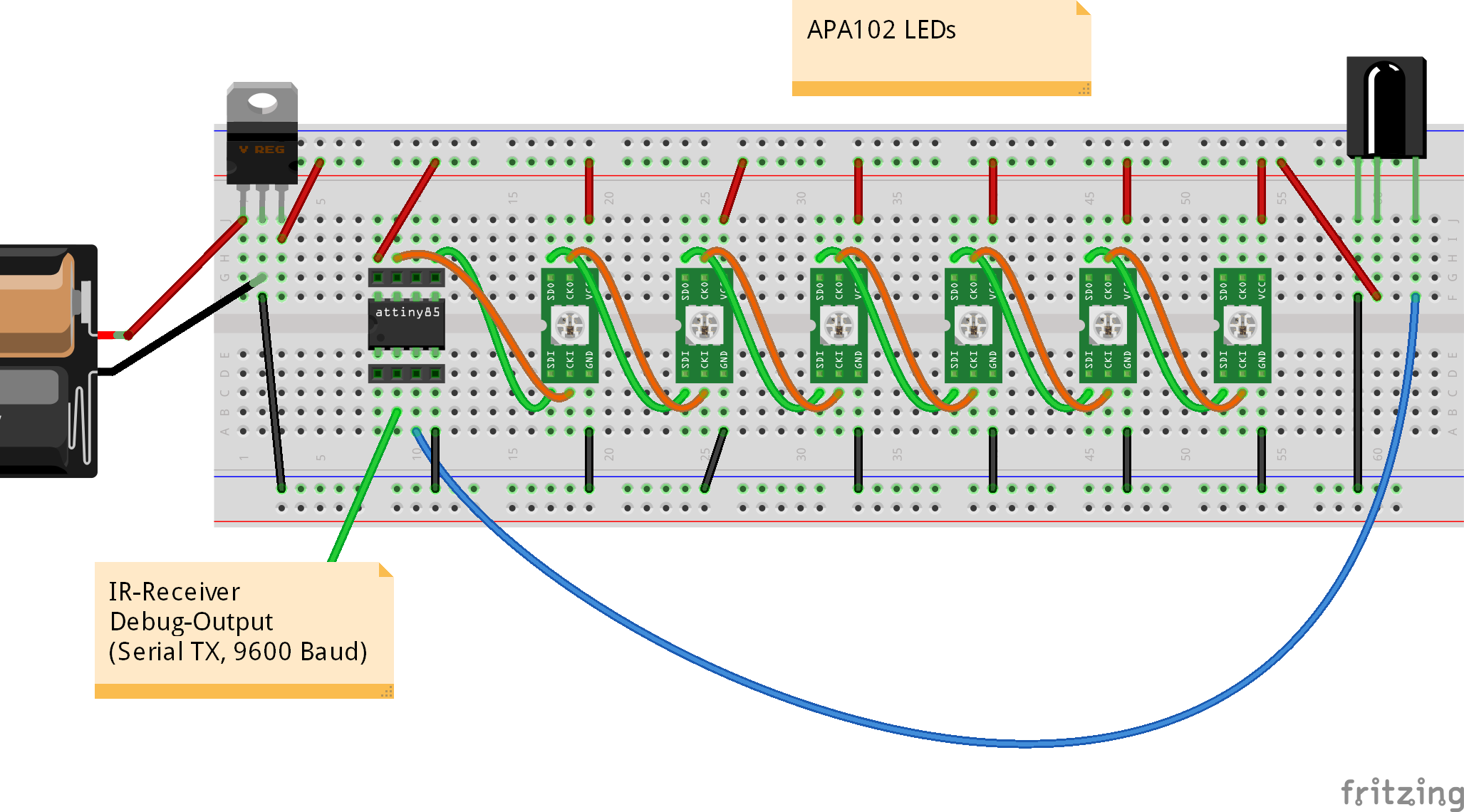
A tiny daisy chain of LEDs, the receiver, the regulator and – since one of the ports was unused – a serial output, printing whatever the IR receiver decodes.
PCB Layout
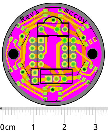 Apart from one other project, I didn’t bother to create PRINTED circuit boards. So far, I usually just used prototype boards or kept stuff on breadboards. But one of the advantages of a tiny circuit is that a tiny PCB is not all that expensive. Layout was done in fritzing, as well. A project of this complexity can be routed by hand in a matter of minutes.
All of the bottom layer is actually just ground plane. All routing happens on the top layer. I was not satisfied with the quality of fritzings ground fill, so I opened up my fritzing file, deserialized the ground layer (which is actually just an SVG) and redrew it in Inkscape. That’s why it shows up in pink, here. It worked out great, but it’s not exactly a simple set of steps.
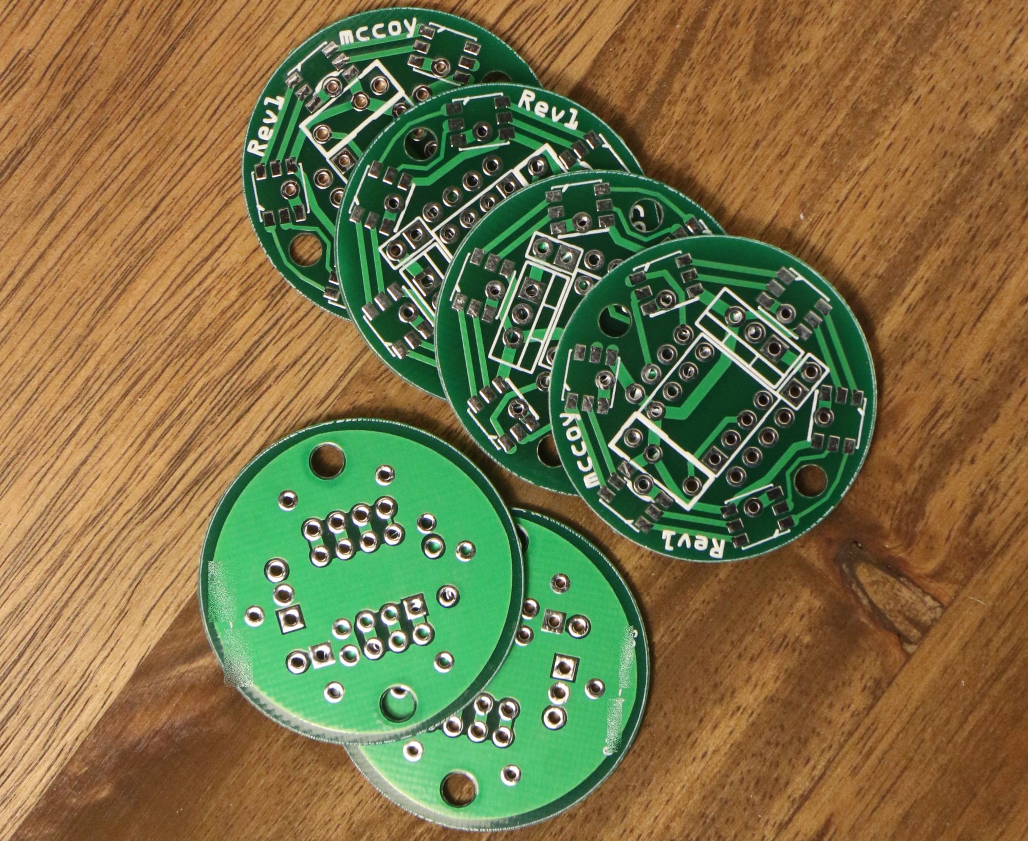
I created gerber files from fritzing and dumped them to Seeedstudio, which worked alright. 10 PCBs cost ~15€ including shipping. Fritzing’s own manufacturing service would have been more expensive (~30 If I remember correctly), but I’m probably going with them for future projects, anyway.
Programming
The program is a combination of TinyDebugSerial, FastLED and tinyIRremote. I modified the latter to only include codes for my specific remote to fit all three into the ATtiny’s tiny memory. The code can be downloaded below. It basically initializes the three parts in setup, and then waits for an IR-Signal in loop.
List of firsts
- first PCB I ordered from gerber files
- first time to solder SMD parts
- first ATtiny project
- first IR-Receiver project
- first project with LDO voltage regulator
- first project to have a documentation video
Files
I love open source. I profit tremendously from it. Both the schematics and the code are released under CC0 / Public Domain License. If you build something from it, let me know!